Every pump installation has a hidden failure mode that engineers don’t always catch until it’s too late — and it announces itself with a sound like gravel rattling around inside the casing. That’s cavitation, and the number that tells you whether you’re heading for it is called Net Positive Suction Head, or NPSH.
What Is NPSH, Really?
Every liquid has a vapor pressure — the pressure at which it turns to gas at a given temperature. Water at 20°C vaporizes at around 2,300 Pa. At 80°C that rises to 47,000 Pa. At 100°C it equals atmospheric pressure, which is why it boils in an open pot.
Inside a pump, the impeller accelerates fluid by dropping its local pressure. If that pressure drops to the fluid’s vapor pressure, the liquid flash-vaporizes and forms bubbles. Those bubbles then travel into a higher-pressure zone, collapse violently, and send shockwaves into the metal. Over time this pits and erodes the impeller. In severe cases it can destroy a pump in a matter of hours.
NPSH is the engineering answer to the question: how much pressure does the fluid arrive at the pump with, above its own tendency to vaporize? The more of it you have, the safer you are.
There are two sides to NPSH:
- NPSHa (available) — determined by your system: the tank pressure, fluid temperature, pipe layout, elevation, and friction losses on the suction side.
- NPSHr (required) — determined by the pump manufacturer, published on the pump curve for each flow rate.
The rule is simple: NPSHa must always exceed NPSHr, with a margin to spare.
The Basic Formula
For most everyday installations — an open tank, cold fluid, straightforward pipework — the basic formula is sufficient:
NPSH_A = H_a \pm H_s - H_f - H_{vP}Where:
- H_a is the absolute pressure head at the suction source — for an open tank, this is atmospheric pressure converted to metres of head (~10.3 m for water at sea level).
- H_s is the static head — positive if the source is above the pump centreline, negative if below (suction lift).
- H_f is the total friction head loss in the suction pipework — every pipe length, valve, elbow, and reducer counts.
- H_{vP} is the vapor pressure head — the fluid’s vapor pressure at operating temperature, converted to metres of head.
Converting pressure to head is straightforward:
H = \frac{P}{\rho \times g}So for cold water at 20°C, the vapor pressure head is just 2,338 / (998 × 9.81) ≈ 0.24 m — almost negligible. For water at 80°C it jumps to nearly 5 m. Temperature is not a detail you can ignore.
The Precise Formula
For pressurised vessels, hot process fluids, high-velocity inlets, or any installation where the margin is tight, the precise formula accounts for more of the physics:
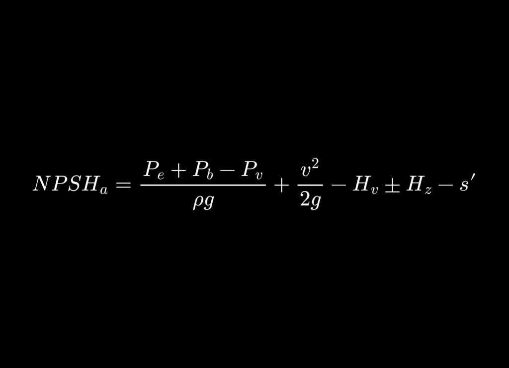
NPSH_a = \frac{P_e + P_b - P_v}{\rho g} + \frac{v^2}{2g} - H_v \pm H_z - s'This unpacks as follows:
(P_e + P_b - P_v) / \rho g — the net pressure available at the suction source, above vapor pressure, expressed as head. P_e is the gauge pressure inside the vessel, P_b is barometric pressure, and P_v is vapor pressure. For an open tank at sea level with cold water, this term alone is about 10.1 m. For a hot pressurised vessel, you add the vessel’s gauge pressure, which can make a substantial difference.
v^2 / 2g — the velocity head at the pump suction flange. Often small, but significant in high-velocity or small-bore systems.
H_v — the velocity head at the suction source surface. This is subtracted because that kinetic energy was already present before the fluid entered the suction pipe; it doesn’t represent additional head available to the pump. For a large tank the surface velocity is negligible.
\pm H_z — the elevation of the source surface relative to the pump centreline. Positive if the source is higher (this head works in your favour), negative if the pump is above the source.
s' — all friction losses in the suction pipework. Same as H_f in the basic formula.
A Worked Example
Take a hot water system: water at 80°C, vessel pressure 50 kPa gauge, the vessel 2 m above the pump centreline, suction friction losses 1.2 m, velocity at the suction flange 2.0 m/s.
At 80°C, water has a density of 972 kg/m³ and a vapor pressure of 47,390 Pa.
The pressure term:
\frac{50{,}000 + 101{,}325 - 47{,}390}{972 \times 9.81} = \frac{103{,}935}{9{,}535} = 10.90 \text{ m}The velocity head at the flange:
\frac{2.0^2}{2 \times 9.81} = 0.20 \text{ m}Putting it together (assuming negligible source velocity, source above pump):
NPSH_a = 10.90 + 0.20 + 2.0 - 1.2 = 11.90 \text{ m}That’s a healthy result. But note how much of it depends on the vessel being pressurised. If this were an open tank at atmospheric pressure with the same hot water, the pressure term would shrink dramatically — and the margin could evaporate.
The Near-Boiling Problem
The most dangerous NPSH scenario is a fluid near its boiling point — condensate return lines, reboiler circuits, hot process tanks. As temperature approaches boiling, vapor pressure approaches atmospheric. In the basic formula, H_{vP} approaches H_a, and they nearly cancel each other out. You can be left with almost zero NPSHa even with a perfectly designed suction system.
The solutions, in rough order of preference:
- Pressurise the suction vessel — adds directly to the pressure term.
- Lower the pump below the vessel — increases H_z.
- Subcool the fluid — even a few degrees drops the vapor pressure significantly.
- Select a low-NPSHr pump — double-suction designs and inducers can achieve NPSHr values of 1–2 m, buying back the margin on the pump side.
Vapor Pressure of Water at a Glance
| Temperature (°C) | Vapor Pressure (Pa) | Vapor Pressure Head (m) |
| 10 | 1,228 | 0.13 |
| 20 | 2,338 | 0.24 |
| 40 | 7,384 | 0.77 |
| 60 | 19,940 | 2.09 |
| 80 | 47,390 | 4.97 |
| 100 | 101,325 | 10.33 |
For any other fluid, always obtain vapor pressure data at the actual operating temperature — not ambient, not the fluid’s rated temperature, the temperature it will be at the pump inlet.
How Much Margin Is Enough?
The Hydraulic Institute (HI Standard 9.6.1) recommends a minimum margin ratio of NPSHa/NPSHr between 1.1 and 1.5, depending on severity of service. As a practical guide:
| Application | Minimum (NPSHa − NPSHr) |
| General industrial | 1.0 m |
| Variable flow systems | 1.5 m |
| Hot or volatile fluids | 2.0–3.0 m |
| High-value or critical equipment | 2.0 m |
These are minimums. Where you have latitude in the design, build in more. Suction conditions are often worse in practice than on paper — partially closed valves, fouled strainers, higher-than-expected fluid temperatures. Margin is cheap insurance.
What Cavitation Looks Like
If you’re diagnosing an existing installation rather than designing a new one, these are the signs:
- A crackling or rattling noise from the pump casing — often described as pumping gravel.
- Fluctuating discharge pressure and flow, particularly at higher flow rates.
- Reduced pump performance that doesn’t match the curve.
- On inspection: pitting and erosion on the impeller, typically on the low-pressure face of the vanes.
Performance drop at high flow is particularly telling. NPSHr rises steeply toward the right end of the pump curve — the same operating point where NPSHa tends to fall as friction losses increase with flow rate. The two curves can cross before you reach the pump’s rated maximum flow.
Common Mistakes
Using gauge pressure instead of absolute. The formula requires absolute pressure throughout. Forgetting to add barometric pressure when using gauge readings is the single most common NPSH calculation error.
Ignoring temperature effects on density. Water at 80°C is about 3% less dense than at 20°C. This affects every head conversion. Use density at the actual operating temperature.
Skipping minor losses. A gate valve, a 90° elbow, a reducer, a strainer — each adds head loss. On a short suction line they can collectively exceed the pipe friction loss.
Reading NPSHr at rated flow only. Check the NPSHr curve across your full operating range, not just the design point. If the system ever runs at high flow — during startup, purging, or demand spikes — the pump’s NPSHr at that point is what matters.
Forgetting altitude. Barometric pressure drops roughly 12 Pa per metre of elevation, or about 1.2 m of water head per 1,000 m altitude. An installation that works comfortably at sea level may cavitate at high altitude with the same fluid and layout.
Summary
NPSH is not a bureaucratic calculation — it is the difference between a pump that runs for decades and one that destroys itself in an afternoon. The available head is set by your system; the required head is set by your pump choice. Your job is to ensure the gap between them stays positive, with enough margin that reality’s imperfections don’t close it.
Get the fluid temperature right, account for every loss on the suction side, check your pressure references are absolute, and build in margin. Everything else follows from that.